 Surface roughness is a measure of high-frequency deviations in the departure of a surface from ideal. Surface roughness can result in unwanted scattering in an optical system and for many optical applications one might think it is always best to minimize surface roughness. However, simply minimizing surface roughness without regard to system wavelength and performance can result in increased costs and longer production times. When choosing specifications for a particular optical component, it is important to consider the function of the component in the context of the entire optical system in which it will be used. A careful analysis of the role surface roughness plays in a system can avoid unnecessary production costs due to over-specification. For example, a 10 Angstrom RMS surface roughness can impact a system operating in the visible region more significantly than a system operating in the mid or far infrared.
Surface roughness definitions and standards
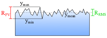
The most common roughness specifications are peak-to-valley (PV) or root-mean-square (RMS) values. PV values are determined by finding the difference between the highest peak (ymax) and lowest valley (ymin) along a surface with height y; . PV values give a good idea of maximum surface variation that may occur and therefore can suggest a surface is much rougher than it is on average. The RMS value is based on the standard deviation of the surface height from the mean value (ymean); . RMS specifications give the overall roughness of the surface while PV gives the maximum deviation at a single spot on the surface. The intended use for an optic determines which specification is most relevant. A good rule of thumb is to think of PV specifications as the “worst-case-scenario” for the optic, while RMS describes the average surface variation. For a detailed discussion of how to use PV and RMS specifications check out this blog post.
The most common surface quality standards are Military Performance Specification MIL-PRF-13830B and the International Organization for Standardization ISO 10110 optical drawing standards. Unfortunately, converting between these two standards is not straightforward and clients often over-specify roughness to be on the safe side when going between standards. Additional confusion arises if both MIL-PRF-13830B cosmetic quality and a surface roughness are specified for a part. These specifications are redundant and only one should be given.
Quantifying surface roughness
Surface roughness is measured through a variety of techniques. Some manufacturers have contact profilometers that physically touch the surface and measure the surface via a fine diamond tip and the oscillation of the lever arm. This technique typically measures along certain lines on the surface. Other profilometers are non-contact and use a laser to measure along a linear portion of the surface. Another approach uses white light interferometry to obtain a surface map of the whole clear aperture or a specific region of the part. In general, it is easiest to perform surface roughness measurements on planar surfaces and more challenging for surfaces with complex curvatures, such as aspheric lenses.
How surface roughness specifications impact your bottom line
Verifying the surface roughness of an ordered part can be prohibitively expensive for some manufacturers. Using a contact method such as a profilometer to measure surface roughness risks surface damage that may render a part unusable. Additionally, contact methods are often slow and only interrogate a small portion of a surface. Non-contact methods, such as white light interferometry, can probe entire surfaces but the equipment necessary for these measurements can be prohibitively expensive for some shops. If shops cannot accurately measure parts to ensure they can meet specified tolerances, then it is impossible for them to reliably guarantee performance. Typically, an optic finished via spindle polish will have a surface roughness in the realm of 10-15 Angstroms. Achieving a super polished surface (1-2 Angstroms) requires more time as well as dedicated manufacturing equipment.
Wavefront distortion and surface roughness
Surface roughness is most important in applications that are sensitive to light scattering. In high power laser systems scattering light in the wrong direction can cause damage to the system or injury to those operating it. A rough surface can scatter laser light and decrease the coherence of a laser beam. Scattered light can also add to background noise and reduce the detection sensitivity of a system. In high energy laser systems, it makes sense to splurge on highly polished optical components to reduce scattering, preserve coherence, and increase sensitivity. In systems where these factors are not critical, it is often better to use lower-cost optical components with a correspondingly less stringent surface roughness specification.
When performing tolerance analysis, it is important to distinguish surface roughness from surface irregularity. While both describe the deviation of a surface from the ideal, surface roughness is typically a higher frequency surface departure than wavefront error. Surface irregularity is a lower frequency variation in the surface form which can result in wavefront distortion but typically does not result in scattering.
Conclusion
It is most cost-effective to understand how an optic is going to be manufactured and tested or alternatively specifying techniques in your drawing or control document. If the surface roughness specification is too tight, it will limit which manufacturers can supply the optic and if a roughness value is specified, then it must be measured. This will also limit which manufacturers can supply the verification data or increase costs because parts will need to be sent to a third party for verification. If the project requires verification, consider Acceptance Quality Level (AQL) testing since the optic may be manufactured as a lot on a common spindle, where the overall surface roughness will be consistent across the lot. This is primarily controlled by polishing speed, pressure, and slurry grit.
For complimentary guidance on your project, contact Ross Optical’s technical team today.